Tuesday, February 21, 2012

ET1003 DIGITAL ELECTRONICS I

Digital Electronics 1 (ET1003) Lab Assignment
School of Electrical & Electronic Engineering

DIGITAL ELECTRONICS 1 2010/2011 Session
Lab Assignment Set No 1:

Design of a BCD decoder for a Common Cathode 7-segment LED

A common output device used for displaying decimal numbers is the 7-segment LED display shown in Fig. 1 below. Each of the segments which is labelled with standard letters from a to g, is an LED (or Light Emitting Diode) arranged physically in a matrix such that a decimal digit is displayed when the appropriate segments are lit. For example to display digit two, the LED segments labelled a,b,g,e and d (as illustrated in Fig 1.) must be lit.
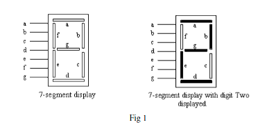
Two types of 7-segment displays are generally available: ‘common cathode’ and ‘common anode’. In the ‘common cathode’ type of 7-segment LED display, a logic High (or 1) must be applied at the segment input pin to light up the segment. For example, to display digit 2 as shown above, logic High must be applied at the input pins of a,b,g,e and d, while the logic levels at f and c must be Low. In the common anode type of 7-segment display, the opposite logic level is required to turn on an LED segment, i.e. a logic Low input will cause the segment to light.

In order to display decimal digits coded in BCD, a BCD-to-7-segment decoder is required as illustrated in fig.2. This device takes BCD inputs and generates at its outputs, the appropriate logic levels for the 7-segment LED display. For example, to display digit ‘2’, the BCD code for decimal 2 which is ‘0010’ must be applied at inputs D C B A of the decoder, with input D being the MSB. The decoder in turn generates the correct logic levels at outputs a, b, c, d, e, f and g so that the correct LED segments are lit to display digit 2.
Task:
Your assignment is to do a paper design of this BCD-to-7-segment decoder for a common cathode display using the least possible number of NAND gates (i.e. an optimum design). You are to assume that only BCD numbers are applied to the inputs of the decoder, i.e. you should take advantage of don’t care conditions. Your solutions must show all the design steps taken, i.e. a description of the task, requirements definition, design approaches such as truth-table(s), simplification using K-maps or Boolean theorems, and the implementation (circuit diagrams) using standard logic symbols. Use a Truth-table format as shown below.


On completion of your paper design, you should use NI Multsim and simulate your circuit to verify that your solution works. You are to demonstrate this simulation and submit the simulation file to your Lecturer by Week 12 during your Lab or Tutorial lesson.

Assessment Distribution
Paper Design: 50%
Simulation File: 30%
Demo & Interview: 20 %
____________________________________________________

Truth-table Answer:

K-map answer:

implementation (circuit diagrams) Ans:


Multisims circuit implementation (circuit diagrams) Ans:

download link for multisim circuit implementation
http://www.mediafire.com/?si92mog4v47okk4
____________________________________________________


School of Electrical & Electronic Engineering


Laboratory Test
Instructions to Students
1.         Read all the instructions and questions carefully.

2.         You are expected to work out your solutions on paper before the day of the test. Marks are given for all the preparatory work, accordingly.

3.         Bring your Notebook, (installed with NI Multisim), completed test paper and Multisim simulation file with you on the day of the test.

4.         You are required to demonstrate your design to your Lecturer in the laboratory according to the instructions given in the test paper.

5.         All efforts have been made to ensure that the ICs, the wires and the digital trainer are fully functional. If you believe that an IC or anything else is faulty, inform your Lecturer and it will be replaced.

6.                  No other help whatsoever will be given to you in getting your circuit working.

There are 7 pages in this Laboratory Test paper.


Laboratory Test:  A 2-bit Adder Circuit

A two bit Adder is a combinational circuit which is able to add two sets of 2-bit numbers  A1 A0 & B1 B0 to produce a sum result which can be up to 3 bits S2 S1 S0.  Figure 1 below illustrates.


As an example, the table below shows a typical set of results for input data as given.

Bit 2
Bit 1
Bit 0
Decimal
Number A
Number B

11
1
= 3
     +
      1
1
= 3
Sum
1
      1
0
= 6

Your tasks in this Lab Test is to design, build and test this 2-bit Adder circuit in a number of sequenced steps starting from a simple half adder circuit, progressing to a full adder circuit and finally to a 2-bit Adder.  Marks will be given progressively at every stage of the test.

Preparatory Work

The following Sections must be completed before you come for the Laboratory Test

The ICs given to you for this Lab Test are as follows:
IC Type
Number given
7408 or 74LS08
1 pc
7432 or 74LS32
1 pc
7486 or 74LS86
1 pc


Section A: Half Adder

A Half Adder adds only two bits A0 and B0 to produce a Sum output S0 and a Carry-out output Cout.  Complete the truth table for the Half Adder given below.

Inputs
Outputs
B0
A0
S0
Cout
0
0


0
1


1
0


1
1


Marks Allocated:
5 Marks
Marks Awarded:
            / 5 Marks


From the truth table you have completed, implement the Half Adder circuit using the least possible number of gates and ICs.  Draw your circuit in the blank space given below.  You are also required to build this circuit and demonstrate its workability to your Lecturer during the Lab Test.


Marks Allocated :
30 Marks
Correct Circuit
/ 5  marks  
Working Circuit
/ 25  marks 


Section B: Full Adder Circuit


The addition of the upper set of bits B1 and A1 requires a 3-bit input as it also includes the carry bit generated from the previous addition, i.e. carry over from the addition of A0 and B0. This requires what is called a full adder, a circuit that adds 3 bits, A1, B1 and the carry-input Cin. This full adder may be designed using the traditional combinational logic approach, using the Truth Table ---> Boolean expressions ---> Karnaugh mapping approach as taught in your lectures. However for this Lab Test, the full adder will not be built using this approach but instead from the use of 2 half adders and a 2-input Or gate connected as shown in the block diagram below. This method results in a simpler circuit for the Full Adder circuit. Using the block diagram, draw your circuit below and on the day of your test, construct and demonstrate its workability to your Lecturer

Marks Allocated :
35 Marks
Correct Circuit
/ 5  marks 
Working Circuit
/ 30  marks 


Section C: 2 Bit Adder Circuit

The 2-Bit Adder circuit can be constructed using a Half Adder connected to a Full adder as shown in the block diagram below. Using this block diagram, complete the circuit of your 2-bit adder circuit in the blank space provided.  Using NI Multisim, capture your completed circuit and save it to your Notebook. In the event that you are unable to get your circuit working on the trainer, you will be required to demonstrate its workability using Multisim to qualify for the marks under “Correct Circuit”.  On your test date, construct this circuit on your logic trainer.  Hence verify its operation in the presence of your Lecturer by completing the truth table given in the following page.  Note that for this circuit, you are required to connect the 2-Bit Adder outputs to one of the 7-Segment digital display on the logic trainer.


Truth Table for verifying correct circuit operation (N.B: To be completed during Test)

Inputs
Outputs
B1
B0
A1
A0
Digit displayed
0
0
0
0

0
0
0
1

0
0
1
0

0
0
1
1

0
1
0
0

0
1
0
1

0
1
1
0

0
1
1
1

1
0
0
0

1
0
0
1

1
0
1
0

1
0
1
1

1
1
0
0

1
1
0
1

1
1
1
0

1
1
1
1


________________________________________________


Full Adder Circuit Answer:


2 Bit Adder Circuit Answer:

download link for multisim circuit implementation
http://www.mediafire.com/?8b8i50vwfbkwqyv

ET1011 INTRODUCTION TO ENGINEERING II

IE II Project – Moving Car Transit

INTRODUCTION

The purpose of this project is to develop a car that can move forward from Station 1 to an assigned Station, reverse automatically and stop after hitting an emergency switch (micro switch) in the forward and reverse direction.

The car must be able to detect and count gantries as it moves forward.  Once the car has gone under a predetermined number of gantries, it will reverse.

The overall specification of your designed car should not exceed 12cm (W), 17cm (L) and 15cm (H).

Each Station shall have an inverted U-shaped piece of Acrylic material which positions at a height of 15cm. The intention is to make the light dimmer at these stations as the car passes through them and interrupt its light dependent resistor.

This project is to be done in groups of 3 to 4 students and a maximum of 6 teams per class.
_______________________________________________

6          Count Limiting Circuit (Student Board)


The Count Limiting Circuit is to be designed and built by each project group. The Circuit should be able to receive the Q0 – Q3 feedback signals, decode them, compare with the reference signal (ie the assigned station as given by your lecturer) and produce the appropriate output signals ie the Up or Down signal to the Counter and Display Circuit and Forward or Reverse signal to the Motion Control Circuit.

Design your circuit based on the loop that your lecturer assigned to your team. Simplify your circuit and try to achieve with minimum possible number of components.

You may use the ICs listed below and they are available in the laboratory.

1) 74LS32 OR gate
2) 74LS08 AND gate
3) 74LS04 NOT gate
4) 74LS02 NOR gate
5) 74LS00 NAND gate
6) 74LS74 D flip flop
7) 2N3904 NPN transistor

Note: The power supply for this project is 9V battery for the electronic circuitry and 3V battery for the motor.


Component List (component required to build a adjustable count limiting circuit )
1. IC 7474
2.  Resistor
3. Pins
4. Stripboard
5. 7400
6. 7432
7. 4way DIL switch


Plan
* CPU and CPD get from seven segment display board
* Clock get from ldr board
* Reverse get from motor board


NETWORK VULNERABILITY & SECURITY TOOLS (ET0521) 2011/12 Semester Two - NVST mini Project

School of Electrical & Electronic Engineering
20/1112 Semester Two - NVST Mini Project


You are an information security professional. You are being engaged by a company as Chief Security Officer (CSO) to conduct security evaluation for the company servers. Your duty is to conduct a series of test on all these servers and services running using the necessary tools to identify the potential risks in these servers and services setup. After that you will recommend the necessary corrective actions to these potential risks. You are given a temporary administrator account to conduct your investigation.

User name : temp
Password : password                                                                                              SAS code: LAB3

1. DNS Server
    Tool use: Command prompt “Nslookup”
    Problem: Typing command “nslookup” on the command prompt (cmd), an attacker will be able to invoke the program and start to obtain data from the name servers because all data in the server will be made available for the attackers upon nslookup command. 

This is a problem because attackers can request the server to transmit all information regarding a domain using zone transfer request from the name server. All these information are beneficial for the attacker because its IP address and other information can be used in an attack (e.g. DoS attacks, an attack against zone’s DNS servers by sending multiple requests to slow down the server.)
    Remedy: Choosing “Only to servers listed on the Name server tab” at Window 2000’s DNS Zone Transfer settings enables zone transfer to be restricted, except for trusted secondary server. This will result into “*Can’t list domain XXX: Query refused”, which also means a secured server. 

Choosing “Name Servers tab” enables trusted secondary server allowed for zone transfer to view all the data information upon nslookup command by keying in their respective compute IP addresses.

To modify zone transfer settings using the Windows interface
1.        Open DNS Manager.
2.        Right-click a DNS zone, and then click Properties.
3.        On the Zone Transfers tab, do one of the following:
·         To disable zone transfers, clear the Allow zone transfers check box.
·         To allow zone transfers, select the Allow zone transfers check box.
4.        If you allowed zone transfers, do one of the following:
·         To allow zone transfers to any server, click To any server.
·         To allow zone transfers only to the DNS servers that are listed on the Name Servers tab, click Only to servers listed on the Name Servers tab.
To allow zone transfers only to specific DNS servers, click Only to the following servers, and then add the IP address of one or more DNS servers.

2. Web Server
     Tool use: iis lockdown tool
     Problem: 
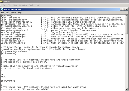
The web server name is shown when an attacker launch an attack using Superscan 4 program to do banner grabbing. This will allow him to find out the web server application at the machine. attackers can retrieve header information of the web server containing the web server application and its current version (i.e. Microsoft IIS/5.0). By gaining such information, it is a problem because attackers will be able to discover the known vulnerabilities of that particular web server and continue to exploit it by sending a malformed URL to the server. Using an IIS version of 5.0, it possess an Unicode extension, which exploit using HTTP protocol and malformed function to transverse directories and executes arbitrary commands on vulnerable web servers. Other unused features included in the server can also pose as a security threat.


     Remedy: IIS Lockdown works by turning off unnecessary features such as web server name, thus reducing attack surface available to attackers.this include renaming the web server name into any other name. This also provide multiple layers of protection against attackers, such as Superscan 4 and URLscan. with customized templates for each supported server role, is integrated into the IIS Lockdown Wizard.


It is necessary to remove the header information of the web server from respond by changing the configuration setting (i.e. RemoveServerHeader=1) in the urlscan folder after installing IIS LockDown tool in Windows 2000 and do a URLScan update after that.

3.   Telnet Server
      Tool use: SSH
      Problem: Telnet enables access to a command-line interface on a remote host and does not encrypt data sent over the connection, which includes usernames and passwords and sends in clear text. This resulted into an unsecured connection
Attackers can gain information by eavesdropping into the connection using Ethereal as all the telnet data captured by Ethereal are sent in clear text and being made available to attackers easily for them to gain access into a network.
     Remedy: Using encryption tools such as mobaSSH (SSH version 2), Install the SSH on server and Putty on client. Using the SSH function from Putty allows all clear texts will be encrypted and therefore, hidden from the attacker. This disables them from retrieving user information and gain access into a network.


4. Password 
    Tool use: At Local Security Settings (Strong password policy)
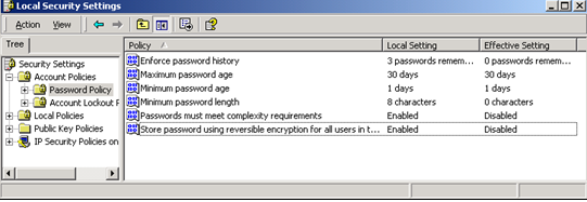
     Problem: Attacker can quickly guess these passwords by using password guessing tools to retrieve the password if it is one of the words in the dictionary. Also, If the password length is too short, it would be a weak password could crack it easily using brute force attack.
     Remedy: By adjusting the configuration settings in the Account Policies (Password Policy and Account Policy), it enables the user’s server account to be more secured., specifying a minimum length and prohibiting the use of dictionary term.
Password should be at least 8 characters long, and should be required to include non-alphanumeric characters.


5. How to close unused port? 
    Tool use: TCP/IP filtering
    Problem: Attackers using port scanning tools (SuperScan 4.0) can easily identify running services on a host and scan for listening ports on a single target host. 

By using SuperScan’s HTML results, all the TCP/UDP ports in use by the server will be easily made known.
Using netstat command at Window 2000 (i.e. netstat –a), a list of ports will be shown upon request. By comparing with the ports listed at the netstat command and the SuperScan HTML results, there will be some ports that are listed in netstat, not listed in SuperScan. This justifies which port are required to be closed or unused.

Attackers can easily gain entry point into target computer and exploits the vulnerability from the open once they are aware which port is available.

     Remedy: To prevent an attacker from discovering open ports on your machine is to close any unused ports using TCP/IP filtering and Periodically run the vulnerability scanning tools against your own networks to identify vulnerabilities before an attacker does.

How to configure TCP/IP security

To configure TCP/IP security:
1.        Click Start , point to Settings , click Control Panel , and then double-click Network and Dial-up Connections .
2.        Right-click the interface on which you want to configure inbound access control, and then clickProperties .
3.        In the Components checked are used by this connection box, click Internet Protocol (TCP/IP) , and then click Properties .
4.        In the Internet Protocol (TCP/IP) Properties dialog box, click Advanced .
5.        Click the Options tab.
6.        Click TCP/IP filtering , and then click Properties .
7.        Select the Enable TCP/IP Filtering (All adapters) check box. When you select this check box, you enable filtering for all adapters, but you configure the filters on a per-adapter basis. The same filters do not apply to all adapters.
8.        There are three columns with the following labels:
TCP Ports
UDP Ports
IP Protocols
In each column, you must select either of the following options:
Permit All . If you want to permit all packets for TCP or UDP traffic, leave Permit All activated. 

Permit Only . If you want to allow only selected TCP or UDP traffic, click Permit Only , clickAdd , and then type the appropriate port in the Add Filter dialog box.
If you want to block all UDP or TCP traffic, click Permit Only , but do not add any port numbers in theUDP Ports or TCP Port column. You cannot block UDP or TCP traffic by selecting Permit Only for IP Protocols and excluding IP protocols 6 and 17.

Saturday, December 31, 2011

GEM Adobe Photoshop CS5


In this Assignment 2, the greatest obstacle that I faced along the way would be deciding on the innovative idea of how to start a piece of digital art. By browsing some of the art work on internet, it provides me with the various ideas and inspirations. However, most of the ideas did not get me anywhere. For instance, taking a picture of an old classic camera is difficult, as it is extremely rare to find one of those these days.

While working on the pictures of the construction vehicles, I had personally made a trip down to a few construction sites to ask for permissions for photo taking. However, they do not allow me to enter any of the construction sites due to their safety rules. Therefore, I have decided to change my project and choose one of the robot figures which is well known as the “Mobile Suits” for my assigment. As a kid, I used to watch robot-related TV programmes such as the Transformers, Gundam and Astro boy. Collecting robot figures eventually became my favourite hobby as I developed a deep interest in them.
I have chosen this specific robot as my assignment because it holds a memorable value to me.  

This robot was a gift from my childhood frend who passed away 3 years ago as my 21th birthday present with both of our names neatly craved on it. I really hope that i could do something on this assignment to make her proud. Despite the obstacles that i faced while working on this assignment, such as time constrains, I somehow managed to overcome all of them through putting in all of my effort.

As to summarise, what I have gained from this assignment are a vital part of our polytechnic education and also an important factor when we start a career in the future. Not only this assessment provide a strong basis for resolving everyday issues, it also undoubtedly helps to handle situations with a positive approach. Any type of work in any industry in any nation has its own type of projects or assignments, so it is important for us to get ready and be prepared for any future challenges that awaits us.


distinction!!  thank a lot.. my childhood friend (Ying hong)